- Home
- Equipment
- Nitto Seiko
- Nitto Seiko Flow Meters
- Nitto Seiko Mass Flow Meter
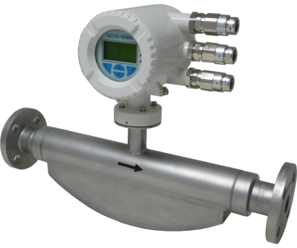


Nitto Seiko Mass Flow Meter
The CLEAN FLOW Mass Flow Meter by Nitto Seiko is a high-performance instrument designed to measure mass flow directly through the sensing of phase differences caused by Coriolis effects in the measuring tube.

Returns & Refunds Policy

Warranty Against Defects

Original Products

Ships Worldwide

Dedicate Support
- Description
- Brand
- Features
- Specifications
- Flow
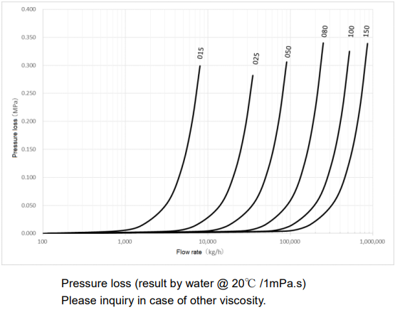
- Pressure loss
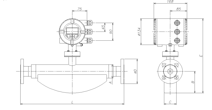
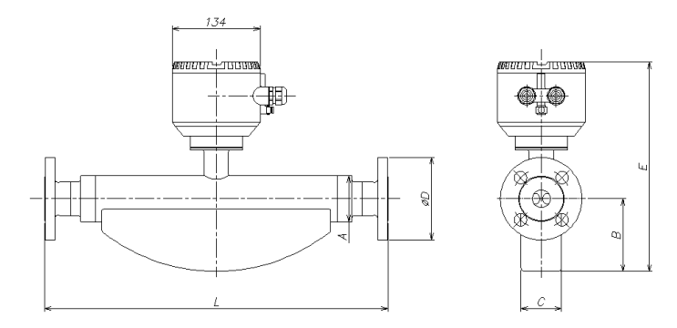
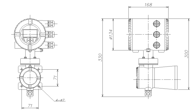
- External dimensions
- Transmitter
- Specification code
The CLEAN FLOW Mass Flow Meter by Nitto Seiko is a high-performance instrument designed to measure mass flow directly through the sensing of phase differences caused by Coriolis effects in the measuring tube. This method ensures accurate and reliable flow measurements, regardless of temperature, pressure, viscosity, density, or flow distribution, making it highly versatile in a variety of industrial applications.
-
Direct Mass Flow Measurement: The meter measures mass flow directly, making it immune to external factors such as temperature, pressure, viscosity, and density changes, which often affect other types of flow meters.
-
Compact Design: The device is designed to be compact, making it easy to integrate into systems with limited space.
-
No Special Fixtures Required: The meter does not require any special fixtures, ensuring easy installation and maintenance.
-
Low Pressure Loss: The new type of measuring tube used in the device ensures minimal pressure loss, improving energy efficiency.
-
High-Functioning Transmitter: The transmitter is equipped with a capacitance touch panel, providing ease of use and an intuitive interface for the operator.
-
Three-Line LCD Display: The three-line LCD display allows for a variety of indication articles to be shown, ensuring clear and easy-to-read data.
-
Backlight for Improved Visibility: The backlight feature ensures excellent visibility, even in low-light environments.
-
Optional Plug-in Card: Users can easily add input and output options through the optional plug-in card, enhancing the flexibility and adaptability of the device.
Sensor
|
Size |
015 |
025 |
050 |
080 |
100 |
150 |
||
|
Nominal diameter |
10A, 15A, 20A, 25A, 40A, 50A, 65A, 80A, 100A, 150A, 200A |
|||||||
|
Connection end |
JIS10K, 20K ASME/ANSI 150, 300, 600 JPI 150, 300, 600 DIN PN16, 40, 63 Tri-clamp |
|||||||
|
Fluid |
Liquid/Gas |
|||||||
|
Flow range |
0 ~ 860,000 Kg/h (6 type) |
|||||||
|
Accuracy |
Volume |
Liquid |
General: Mass flow ±0.4% Volume flow ±0.4% High accuracy: Mass flow ±0.15% (±0.1%option) Volume flow ±0.15% |
|||||
|
Gas |
General: Mass flow ±1.0% High accuracy: Mass flow ±0.5% |
|||||||
|
Density |
Liquid |
General: 0.010kg/L High accuracy: 0.002kg/L (0.001kg/L option) |
||||||
|
Temperature |
General: -50 ~ 160 ℃ High accuracy: -50 ~ 205 ℃ Explosion-proof type is depending on the specification |
|||||||
|
Pressure |
Depending on the connection end |
|||||||
|
Wetted parts material |
Stainless steel (Standard), Alloy C (Option) |
|||||||
|
Explosion-proof |
ATEX / IECEx, cFMus, TIIS (Applying) |
|||||||
Transmitter
|
Power |
100 ~ 240V AC, 50/60Hz 11 ~ 30V DC |
|
Power consumption |
20W |
|
Protection level |
Unit type : IP65 / IP67, NEMA 4X Remote type: IP65 / IP67 / IP68 (Sensor only, Immersion depth 5m), NEMA 4X |
|
Housing material |
Aluminum Stainless (Remote type: Option) |
|
Output signal |
Analog: 4-20mA DC (Active mode or Passive mode) Digital: 2 points (Pulse or switch) (Passive mode) HART (Protocol Ver. 7.1) |
|
Dumping |
0.8 sec. (Avilable setting 0.2 ~100 sec) |
|
Low cut-off |
1% of Max. flow rate. (Available setting 0~5%) |
|
Transmission distance |
Max. 200m (Remote type) |
Liquid mesurement
|
Size |
015 |
025 |
050 |
080 |
100 |
150 |
|
|
Flow range |
MASS flow[kg/h] |
0~8,000 |
0~35,000 |
0~90,000 |
0~250,000 |
0.~560,000 |
0~860,000 |
|
Volume flow [L/h](※1) |
0~8,000 |
0~35,000 |
0~90,000 |
0~250,000 |
0.~560,000 |
0~860,000 |
|
|
(※1)Volume flow is according to the 1g/mL of density. In case of other than 1mg/mL Volume flow = Mass flow / Density. |
|||||||
|
Zero-stability [kg/h] |
0.64 |
2.16 |
7.2 |
20 |
41.6 |
68.8 |
|
Basic accuracy
|
Model |
430 (General type) |
450 (High accuracy type) |
|
Mass flow (Liquid) |
±0.4% ±0.25% (Option) ±0.20% (Option) |
±0.15% ±0.10% (Option) |
|
Mass flow (Gas) |
±1.0% |
±0.5% |
|
Volume flow |
±0.4% ±0.25% (Option) ±0.20% (Option) |
±0.15% |
|
Repeatibility (volume) |
Refer to below table |
|
|
Density (Liquid) |
0.010kg/L |
0.002kg/L 0.001kg/L |
|
Repeatibility (density) |
0.002kg/L |
0.002kg/L 0.001kg/L |
Measuring accuracy
|
|
Max. measuring accuracy |
Repeatability |
|
|
1 |
±General accuracy |
±1/2×General accuracy |
|
|
2 |
|
±(Zero-stability/Measured value)×100% |
±1/2×(Zero-stability/Measured value)×100% |
|
Meter size |
Size (mm) |
Approx. weight (kg) |
|||
|
A |
B |
C |
E |
||
|
015 |
φ44.5 |
77 |
46 |
340 |
9 |
|
025 |
φ69.5 |
103 |
62 |
379 |
11 |
|
050 |
φ99 |
125 |
80 |
416 |
27 |
|
080 |
φ155 |
183 |
123 |
505 |
71 |
|
100 |
φ185 |
261 |
168 |
603 |
123 |
|
150 |
□260 |
320 |
205 |
691 |
181 |
Remote type
|
Meter size |
Size (mm) |
Approx. weight (kg) |
|||
|
A |
B |
C |
E |
||
|
015 |
φ44.5 |
77 |
46 |
340 |
9 |
|
025 |
φ69.5 |
103 |
62 |
379 |
11 |
|
050 |
φ99 |
125 |
80 |
416 |
27 |
|
080 |
φ155 |
183 |
123 |
505 |
71 |
|
100 |
φ185 |
261 |
168 |
603 |
123 |
|
150 |
□260 |
320 |
205 |
691 |
181 |
015 sensor connection standard
|
Connection end |
Specification code |
L(mm) |
D(mm) |
|
10A JIS10K |
015E1J1 |
385 |
90 |
|
15A JIS10K |
015R0J1 |
385 |
95 |
|
1/2” CL150 (ASME B 16.5) |
015R0A1 |
435 |
89 |
|
1/2” CL300 (ASME B 16.5) |
015R0A3 |
421 |
95 |
|
20A JIS10K |
015R1J1 |
421 |
100 |
|
3/4” CL150 (ASME B 16.5) |
015R1A1 |
421 |
98 |
|
Conform to DIN 32676 1/2” Tri-clamp |
015R0T1 |
413 |
34 |
|
Conform to ASME BPE 1/2” Tri-clamp |
015R0T3 |
433 |
25 |
025 sensor connection standard
|
Connection end |
Specification code |
L(mm) |
D(mm) |
|
20A JIS10K |
025E1J1 |
576 |
100 |
|
3/4” CL150 (ASME B 16.5) |
025E1A1 |
575 |
98 |
|
25A JIS10K |
025R0J1 |
525 |
125 |
|
1” CL150 (ASME B 16.5) |
025R0A1 |
575 |
108 |
|
1” CL300 (ASME B 16.5) |
025R0A3 |
576 |
124 |
|
40A JIS10K |
025R2J1 |
576 |
140 |
|
1-1/2” CL150 (ASME B 16.5) |
025R2A1 |
576 |
127 |
|
In accordance with DIN 32676 1” Tri-clamp |
025R0T1 |
590 |
50.5 |
|
In accordance with ASME BPE 1” Tri-clamp |
025R0T3 |
590 |
50.4 |
050 sensor connection standard
|
Connection end |
Specification code |
L(mm) |
D(mm) |
|
40A JIS10K |
050E1J1 |
763 |
140 |
|
1-1/2” CL150 (ASME B 16.5) |
050E1A1 |
763 |
127 |
|
1-1/2” CL300 (ASME B 16.5) |
050E1A3 |
756 |
156 |
|
50A JIS10K |
050R0J1 |
715 |
155 |
|
2” CL150 (ASME B 16.5) |
050R0A1 |
715 |
152 |
|
2” CL300 (ASME B 16.5) |
050R0A3 |
763 |
165 |
|
65A JIS10K |
050R1J1 |
763 |
175 |
|
2-1/2” CL150 (ASME B 16.5) |
050R1A1 |
756 |
178 |
|
In accordance with DIN 32676 2” Tri-clamp |
050R0T1 |
740 |
64 |
|
In accordance with ASME BPE 2” Tri-clamp |
050R0T3 |
740 |
63.9 |
080 sensor connection standard
|
Connection end |
Specification code |
L(mm) |
D(mm) |
|
65A JIS10K |
080E1J1 |
910 |
175 |
|
2-1/2” CL300 (ASME B 16.5) |
080E1A3 |
920 |
178 |
|
80A JIS10K |
080R0J1 |
870 |
185 |
|
3” CL150 (ASME B 16.5) |
080R0A1 |
880 |
191 |
|
3” CL300 (ASME B 16.5) |
080R0A3 |
895 |
210 |
|
100A JIS10K |
080R1J1 |
1060 |
210 |
|
4” CL150 (ASME B 16.5) |
080R1A1 |
880 |
229 |
|
In accordance with DIN 32676 3” Tri-clamp |
080R0T1 |
910 |
106 |
|
In accordance with ASME BPE 3” Tri-clamp |
080R0T3 |
910 |
90.9 |
100 sensor connection standard
|
Connection end |
Specification code |
L(mm) |
D(mm) |
|
80A JIS10K |
100E1J1 |
1275 |
185 |
|
3” CL300 (ASME B 16.5) |
100E1A3 |
1244 |
210 |
|
100A JIS10K |
100R0J1 |
1150 |
210 |
|
4” CL150 (ASME B 16.5) |
100R0A1 |
1144 |
229 |
|
4” CL300 (ASME B 16.5) |
100R0A3 |
1324 |
254 |
|
150A JIS10K |
100R2J1 |
1300 |
280 |
|
6” CL150 (ASME B 16.5) |
100R2A1 |
1330 |
279 |
Note) This size is for major item. Unavailable for manufacturing depend on the combination.
150 sensor connection standard
|
Connection end |
Specification code |
L(mm) |
D(mm) |
|
4” PN16 (EN 1092-1) |
150E2D2 |
1569 |
220 |
|
6” PN16 (EN 1092-1) |
150R0D2 |
1421 |
285 |
|
6” CL150 (ASME B 16.5) |
150R0A1 |
1485 |
279 |
|
6” CL300 (ASME B 16.5) |
150R0A3 |
1505 |
318 |
|
8” CL150 (ASME B 16.5) |
150R2A1 |
1650 |
343 |
|
8” CL300 (ASME B 16.5) |
150R2A3 |
1670 |
381 |
Note) This size is for major item. Unavailable for manufacturing depend on the combination.
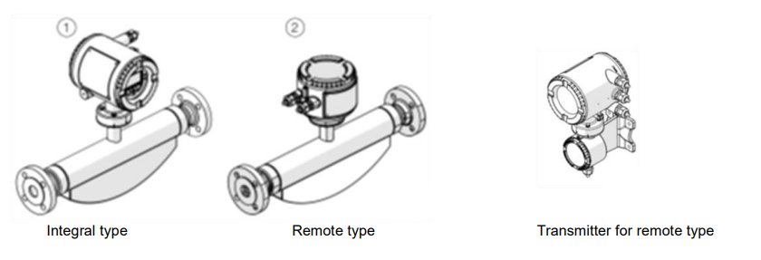
Transmitter for remote type (Type FT)
- Indication contents
Mass flow, Volume flow, Density, Temperature, and any others (Available for select).
4 kind of monitor for operator can be set, and it can indicate several measuring result simultaneously. Indicator has 3 line LCD, and variety of indication is available.
- Operation
Operated by capacitance touch panel through the glass is available. Set according to the menu by 4 operation keys.
- Standard output
Analog output: 1 point (4~20mADC/HART7) Digital output: 2 points (Pulse, frequency)
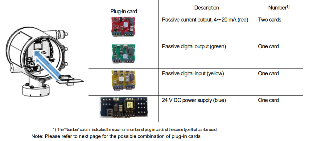
- Optional plug-in cards (for additional output)
The transmitter has two slots in which plug-in cards can be inserted to provide additional inputs and outputs.
The slots are located on the transmitter motherboard and can be accessed after removing the front housing cover.
The possible combination of plug-in cards
|
Output code |
Additional output code |
Slot OC1 Terminals V1 / V2 |
Slot OC2 Terminals V3 / V4 |
|
|
Output 1 |
Output 2 |
|||
|
G0 |
— |
— |
— |
— |
|
G1 |
× |
— |
24 V DC power supply (blue) |
— |
|
G2 |
— |
× |
— |
Passive current output, 4~20 mA (red) |
|
G3 |
× |
× |
Passive current output, 4~20 mA (red) |
Passive current output, 4~20 mA (red) |
|
G0 |
DRT |
DSN |
24 V DC power supply (blue) |
Passive digital input (yellow) |
|
G0 |
DRT |
DSG |
24 V DC power supply (blue) |
Passive digital output (green) |
|
G0 |
DRT |
DSA |
24 V DC power supply (blue) |
Passive current output, 4~20 mA (red) |
|
G0 |
DRN |
— |
Passive digital input (yellow) |
— |
|
G0 |
DRN |
DSG |
Passive digital input (yellow) |
Passive digital output (green) |
|
G0 |
DRN |
DSA |
Passive digital input (yellow) |
Passive current output, 4~20 mA (red) |
|
G0 |
DRG |
DSN |
Passive digital output (green) |
Passive digital input (yellow) |
|
G0 |
DRG |
DSA |
Passive digital output (green) |
Passive current output, 4~20 mA (red) |
Terminal block
- IP rating
In accordance with EN 60529:IP65/IP67, NEMA4X
- Vibration
In accordance with EN 60068-2
10~58Hz, Max deflection 0.15mm(Peak load) 58~150Hz, Max. acceleration 2G(Peak load)
- Ambient temperature
Standard:-20~70℃ Option:-40~70℃
Note) When operating below -20℃, visibility of the LCD display may be worse.
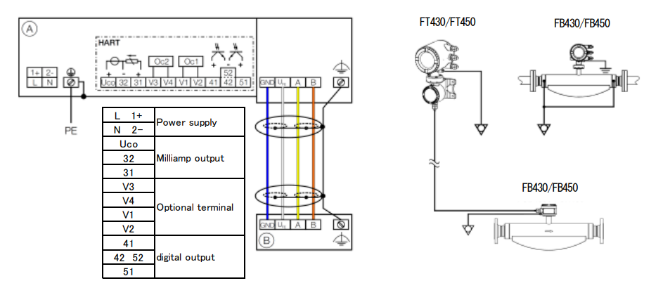
- Signal cable (Remote type: between sensor and transmitter) Impedance 100~200Ω
Withstand voltage 120V Outer diameter 6~12mm
Cable design 4 core shielded cable (2 wire pairs as a star-quad cable) Max. signal cable length
|
0.25mm2 |
: |
50m |
|
0.34mm2 |
: |
100m |
|
0.50mm2 |
: |
150m |
|
0.75mm2 |
: |
200m |
Power
|
AC Power Terminal Operating voltage Power consumption |
: : : |
L/N 100~240VAC 50/60Hz 20VA |
|
DC Power Terminal |
: |
1+/2- |
|
Operating voltage |
: |
11~30VDC |
|
Power consumption |
: |
20W |
Output
Standard output
Current output
|
Current output |
Active mode |
Passive mode |
|
Terminal |
Uco(+)/32(-) |
31(+)/32(-) |
|
Output signal |
4~20mADCor4~12~20mADC Switchable |
4~20mADC |
|
Load resistance |
250~300Ω |
250~600Ω |
|
Source voltage |
- |
12~30V |
|
Measuring error |
0.1% or less of measured value |
|
Digital output
|
Digital output |
Pulse/frequency output (passive) |
Binary output (passive) |
|
Terminal |
41(+)/42(-)、51(+)/52(-) |
41(+)/42(-)、51(+)/52(-) |
|
Output “closed” |
Voltage 3VDC or less 2.5kHz or less:2~30mA More than 2.5kHz:10~30mA |
Voltage 3VDC or less 2~30mA |
|
Output “open” |
Voltage 16~30VDC 0.2mA or less |
Voltage 16~30VDC 0.2mA or less |
|
Max. frequency |
10.5kHz |
- |
|
Pulse width |
0.1~2,000ms |
- |
Option output
Option (by plug-in card)
Passive current output (red)
|
Terminal |
V1(+)/V2(-)、V3(+)/V4(-) |
The plug-in card can be used in slot OC1 or OC2 |
|
Output signal |
4~20mA |
|
|
Load resistance |
250~600Ω |
|
|
Source voltage |
12~30VDC |
|
|
Measuring error |
0.1% or less of measured value |
Digital output (green): Binary output (Passive)
|
Terminal |
V1/V2、V3/V4 |
The plug-in card can be used in slot OC1 or OC2 |
|
Output “closed” |
Voltage 3VDC or less 2~30mA |
|
|
Output “open” |
Voltage 16~30VDC 0.2mA or less |
Digital input (Yellow)
|
Terminal |
V1(+)/V2(-)、V3(+)/V4(-) |
The plug-in card can be used in slot OC1 or OC2 |
|
Input “ON” |
Voltage 16V~30VDC |
|
|
Input “OFF” |
Voltage 3VDC or less |
|
|
Internal resistance |
6.5kΩ |
24VDC Power supply (blue)
|
Terminal |
V1(+)/V2(-) |
The plug-in card can be used in slot OC1 only. |
|
Function |
For active connection of passive outputs |
|
|
Output voltage |
24VDC at 0mA 17VDC at 25mA |
|
|
Load rating |
25mA, permanently short circuit-proof |
|
Article |
Specification code |
Note |
||||||||||
|
Model |
FB450 |
|
Coliolis Mass flow meter / High accuracy type |
|||||||||
|
FB430 |
|
Coliolis Mass flow meter / General type |
||||||||||
|
Explosion Protection Certificate |
Y0 |
|
General Purpose |
|||||||||
|
A2 |
|
ATEX/IECEx (Zone 2/22) |
||||||||||
|
A1 |
|
ATEX/IECEx (Zone 1/21) |
||||||||||
|
F2 |
|
cFMus version Class 1 Div. 2 (Zone 2/21) |
||||||||||
|
F1 |
|
cFMus version Class 1 Div. 1 (Zone 1/21) |
||||||||||
|
Transmitter type / Material / Cable Gland |
Y0 |
|
When select "Unit type" |
|||||||||
|
U1 |
|
Remote type/Aluminum/1-M20×1.5 |
||||||||||
|
U2 |
|
Remote type/Aluminum/1-NPT1/2 |
||||||||||
|
A1 |
|
Remote type/Stainless/1-M20×1.5 |
||||||||||
|
A2 |
|
Remote type/Stainless/1-NPT1/2 |
||||||||||
|
Meter size / Connection size |
015E1 |
|
015/10A(3/8B) |
|||||||||
|
015R0 |
|
015/15A(1/2B) : Standard |
||||||||||
|
015R1 |
|
015/20A(3/4B) |
||||||||||
|
025E1 |
|
025/20A(3/4B) |
||||||||||
|
025R0 |
|
025/25A(1B) : Standard |
||||||||||
|
025R2 |
|
025/40A(1-1/2B) |
||||||||||
|
050E1 |
|
050/40A(1-1/2B) |
||||||||||
|
050R0 |
|
050/50A(1B) : Standard |
||||||||||
|
050R1 |
|
050/65A(2-1/2B) |
||||||||||
|
080E1 |
|
080/65A(2-1/2B) |
||||||||||
|
080R0 |
|
080/80A(3B) : Standard |
||||||||||
|
080R1 |
|
080/100A(4B) |
||||||||||
|
100E1 |
|
100/80A(3B) |
||||||||||
|
100R0 |
|
100/100A(4B) : Standard |
||||||||||
|
100R2 |
|
100/150A(6B) |
||||||||||
|
150E2 |
|
150/100A(4B) |
||||||||||
|
150R0 |
|
150/150A(6B) : Standard |
||||||||||
|
150R2 |
|
150/200A(8B) |
||||||||||
|
Process Connection Type |
J1 |
|
Flange JIS 10K |
|||||||||
|
J2 |
|
Flange JIS 20K |
||||||||||
|
D2 |
|
Flange DIN PN16 |
||||||||||
|
D4 |
|
Flange DIN PN40 |
||||||||||
|
D5 |
|
Flange DIN PN63 |
||||||||||
|
D6 |
|
Flange DIN PN100 |
||||||||||
|
A1 |
|
Flange ANSI/ASME B16.5 Class 150 |
||||||||||
|
A3 |
|
Flange ANSI/ASME B16.5 Class 300 |
||||||||||
|
A6 |
|
Flange ANSI/ASME B16.5 Class 600 |
||||||||||
|
A7 |
|
Flange ANSI/ASME B16.5 Class 900 |
||||||||||
|
A8 |
|
Flange ANSI/ASME B16.5 Class 1500 |
||||||||||
|
T1 |
|
In accordance with DIN 32676 Tri-clamp |
||||||||||
|
T3 |
|
In accordance with ASME BPE Tri-clamp |
||||||||||
|
F1 |
|
In accordance with DIN 11851 Fitting |
||||||||||
|
Material of Wetted Parts |
A1 |
|
Stainless steel |
|||||||||
|
C1 |
|
Ni-Alloy (Alloy-C) |
||||||||||
|
Flow Calibration |
A |
|
Flow forward:Liquid±0.4 %, Gas:±1.0 %・・・・・・General type |
|||||||||
|
B |
|
Flow forward:Liquid±0.25 %, Gas:±1.0 %・・・・・General type |
||||||||||
|
E |
|
Flow forward:Liquid±0.2 %, Gas:±1.0 %・・・・・・General type |
||||||||||
|
C |
|
Flow forward:Liquid±0.15 %, Gas:±0.5 %・・・・・High accuracy type |
||||||||||
|
D |
|
Flow forward:Liquid±0.1 %, Gas:±0.5 %・・・・・・High accuracy type |
||||||||||
|
J |
|
Flow forward/reverse:Liquid±0.4 %, Gas:±1.0 %・・・・・・General type |
||||||||||
|
K |
|
Flow forward/reverse:Liquid±0.25 %, Gas:±1.0 %・・・・・General type |
||||||||||
|
N |
|
Flow forward/reverse:Liquid±0.2 %, Gas:±1.0 %・・・・・・General type |
||||||||||
|
L |
|
Flow forward/reverse:Liquid±0.15 %, Gas:±0.5 %・・・・・High accuracy type |
||||||||||
|
M |
|
Flow forward/reverse:Liquid±0.1 %, Gas:±0.5 %・・・・・・High accuracy type |
||||||||||
|
Density Calibration |
1 |
|
Density 10 g/L・・・・・General type |
|||||||||
|
3 |
|
Density 2 g/L・・・・・・High accuracy type |
||||||||||
|
4 |
|
Density 1 g/L・・・・・・High accuracy type |
||||||||||
|
9 |
|
Others |
||||||||||
|
Transmitter Type / Material / Cable Grand |
D1 |
|
Unit type/Aluminum/3-M20×1.5 |
|||||||||
|
D2 |
|
Unit type/Aluminum/3-NPT1/2 |
||||||||||
|
D5 |
|
Unit type/Aluminum/3-NPT1/2(Explosion protection) |
||||||||||
|
D6 |
|
Unit type/Aluminum/3-M20×1.5(Explosion protection) |
||||||||||
|
Y0 |
|
When select "Remote type" |
||||||||||
|
Output |
G0 |
|
Current output 1(AorP), Digital output 1&2(P)、HART |
|||||||||
|
G1 |
|
Current output 1(AorP), Digital output 1&2(P)、24VDC loop supply、HART |
||||||||||
|
G2 |
|
Current output 1(A), Digital output 1&2(P), current output 2(P)、HART |
||||||||||
|
G3 |
|
Current output 1(A), Digital output 1&2(P), current output 2&3(P)、HART |
||||||||||
|
Y0 |
|
Without: when select remote type |
||||||||||
|
Power supply |
A |
100~230VAC |
||||||||||
|
C |
11~30VDC |
|||||||||||
|
Y |
Without: when select remote type |
|||||||||||
Sensor option
|
Article |
Additional specification code |
Note |
|||||||
|
Additional output 1 |
DRN |
|
1×Digital input |
||||||
|
DRG |
|
1×Digital output |
|||||||
|
DRA |
|
1×Analog output(P)(4~20mA) |
|||||||
|
DRT |
|
24VDC transmitter loop power supply |
|||||||
|
Additional output 2 |
DSN |
|
1×Digital input |
||||||
|
DSG |
|
1×Digital output |
|||||||
|
DSA |
|
1×Analog output(P)(4~20mA) |
|||||||
|
Special operation mode |
N6 |
|
Standard + DensiMass : concentration measurement :only 450 type |
||||||
|
N5 |
|
Standard + Filling application |
|||||||
|
N7 |
|
VeriMass function: Meter verification : omly 450 type |
|||||||
|
Pressure-resistance Sensor Housing |
PR5 |
|
Max. burst pressure 6MPa (Include tower length extension) |
||||||
|
PR6 |
|
Max. burst pressure 10MPa(Include tower length extension):Meter size 015 |
|||||||
|
PR7 |
|
Max. burst pressure 15MPa(Include tower length extension):Meter size 015 |
|||||||
|
Signal Cable Length |
SC0 |
|
Without |
||||||
|
SC1 |
|
5m |
|||||||
|
SC2 |
|
10m |
|||||||
|
SC4 |
|
20m |
|||||||
|
SC5 |
|
25m |
|||||||
|
SC6 |
|
30m |
|||||||
|
SC8 |
|
40m |
|||||||
|
SCA |
|
50m |
|||||||
|
SCE |
|
100m |
|||||||
|
SCG |
|
150m |
|||||||
|
SCJ |
|
200m |
|||||||
|
TAG No. Plate |
T1 |
|
With TAG No. Plate |
||||||
|
Anmbient Temperature Range |
TA9 |
|
-40~70℃ |
||||||
|
Extend Tower Length |
TE1 |
Tower length extension 1, Meter insukation Single |
|||||||
|
TE2 |
Tower length extension 2, Meter insukation Double |
||||||||
Note) P:Passive mode
Remote type (Transmitter)
|
Article |
Specification code |
Note |
|||||
|
Model |
FT450 |
|
Coliolis Mass flow meter High accuracy type |
||||
|
FT430 |
|
Coliolis Mass flow meter General type |
|||||
|
Explosion Protection Certificate |
Y0 |
|
General Purpose |
||||
|
A2 |
|
ATEX/IECEx (Zone 2/22) |
|||||
|
A1 |
|
ATEX/IECEx (Zone 1/21) |
|||||
|
F2 |
|
cFMus version Class 1 Div 2(Zone 2/21) |
|||||
|
F1 |
|
cFMus version Class 1 Div 1(Zone 1/21) |
|||||
|
Transmitter type / Material / Cable Grand |
R1 |
|
Remote type/Aluminum/1-M20×1.5 |
||||
|
R2 |
|
Remote type/Aluminum/1-NPT1/2 |
|||||
|
R5 |
|
Remote type/Staineless/1-M20×1.5 |
|||||
|
R6 |
|
Remote type/Staineless/1-NPT1/2 |
|||||
|
Output |
G0 |
|
Current output 1(AorP), Digital output 1&2(P)、HART |
||||
|
G1 |
|
Current output 1(AorP), Digital output 1&2(P), 24VDC loop power, HART |
|||||
|
G2 |
|
Current output 1(A), Digital output 1&2(P), Current output 2(P), HART |
|||||
|
G3 |
|
Current output 1(A), Digital output 1&2(P), Current output2&3(P), HART |
|||||
|
Power supplu |
A |
|
100~230VAC |
||||
|
C |
11~30VDC |
||||||
Option -
|
Mounting Bracket Shape/ Material |
B1 |
|
2B Pipe mounting / Carbon steel |
||
|
Additional output 1 |
DRN |
|
1×Digital input |
||
|
DRG |
1×Digital output |
||||
|
DRA |
1×Analog output(P)(4~20mA) |
||||
|
DRT |
24VDC transmitter loop power supply |
||||
|
Additional output 2 |
DSN |
|
1×Digital input |
||
|
DSG |
1×Digital output |
||||
|
DSA |
1×Analog output(P)(4~20mA) |
||||
|
TAG No. Plate |
T1 |
With TAG No.Plate |
|||
Note) A: Active mode P: Passive mode

