- Home
- Equipment
- Nitto Seiko
- Nitto Seiko Flow Meters
- Nitto Seiko Ultrasonic Flow Meter
.webp)

.webp)
Nitto Seiko Ultrasonic Flow Meter
This flow meter operates based on the propagation time difference method, which detects variations in the ultrasonic signal propagation time caused by changes in liquid flow speed within a conduit.

Returns & Refunds Policy

Warranty Against Defects

Original Products

Ships Worldwide

Dedicate Support
- Description
- Brand
- Features
- Specifications
- Measurement Principle
- Characteristic of Accuracy
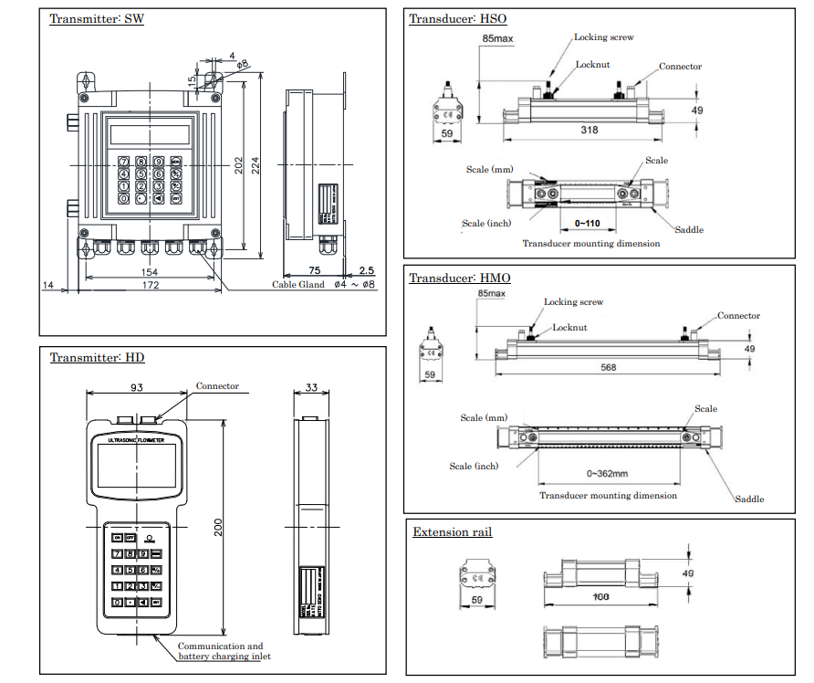
- External Dimension
- Caution for Installation
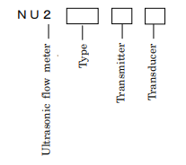
- Model & Specification Code
This flow meter operates based on the propagation time difference method, which detects variations in the ultrasonic signal propagation time caused by changes in liquid flow speed within a conduit.
-
Clamp-On Design: The meter is installed externally on a pipe, making it ideal for measuring liquid flow without the need to disrupt the system or worry about the material’s corrosiveness.
-
Non-Wetted Measurement: Since the meter does not come into direct contact with the liquid, it is immune to issues like corrosion or contamination of the fluid. Additionally, it is unaffected by pressure and conductivity, ensuring reliable readings across various liquid types.
-
Portable & Convenient:
- Hand-Held Type: Compact, lightweight, and equipped with a rechargeable battery, offering up to 10 hours of continuous operation. This portable option is perfect for on-the-go measurements and inspections.
- Wall-Mount Type: A stable option for permanent installations, suitable for continuous monitoring of fluid flow.
-
Installation Flexibility: Easily installed on existing pipelines, and it can be applied to a range of pipe sizes with adjustments.
-
Simple Operation: Equipped with a user-friendly large ten-key interface, making it easy to operate.
-
Versatile Application: Suitable for measuring a wide variety of liquids, including those in small-sized piping systems. The meter can be adapted for different pipe diameters, making it versatile for various applications.
Benefits:
- No Pipe Modification: Installation does not require cutting or altering existing pipes.
- Durability: The external measurement method avoids wear and tear on the meter, extending its service life.
- Cost-Effective: No need for special coatings or materials, and it avoids the costs associated with cutting into pipes or dealing with internal probes.
For transducer
|
Article |
Contents |
|
Measured liquid |
Homogeneity liquid of which ultrasonic can propagate. (Water, Sea water, Industrial water, Acid, Alkali, Alcohol, etc) |
|
Turbidity |
10,000ppm or less |
|
LiquidTemp. |
-30~+90℃ (Same as ambient Temp. of transducer) |
|
Nominal size |
15~600mm (HS0:15~100mm, HM0:50~600mm) |
|
Material of pipe and lining |
Pipe shall be penetrated material by ultrasonic such as Copper, Stainless, PVC, Ductile iron. Lining must adhere to original pipe. (Lining material: Tar-epoxy, Mortar, Rubber, etc.) |
|
Flow rate range |
0~±10m/s |
|
Nos. of traverse line |
1 line |
|
Method |
Propagation time difference by ultrasonic pulse |
|
Accuracy (Calibrated accuracy at factory) |
±2.0% of indicated value (In case of less than 2m/s of flow rate, accuracy is ±0.04m/s) Note) It is required the pipe filled with liquid, and ideal velocity distribution. Note) It is required longer straight pipe than specified. |
|
Protection level |
IP67 |
|
Length of code |
5m as standard. (Please inquiry in case more length is required) |
For transmitter
|
|
Article |
Contents |
|
||
|
Component |
Wall mount type |
Hand held type |
|||
|
Power |
For AC: 100~220V AC±10% 50/60Hz For DC: 24V DC±10% |
100~220V AC±10% 50/60Hz 10 Hrs operation is available at full charge. |
|||
|
Power consumption |
1.5W or less |
2W or less |
|||
|
Ambient Temp. |
-10~+60℃ (Humidity 85% or less) |
||||
|
Atomosphere |
Avoid direct sunshine, radiant heat, corrosive environment, and explosive atomosphere |
||||
|
Analog output |
Kind of signal |
4~20mADC |
|
||
|
Converted Precision |
0.1% |
||||
|
Arrowable load resistance |
750Ω以下 |
||||
|
Open collector output |
Setting frequency |
1~9,999Hz |
|||
|
Current-V oltage |
DC80V、100mA or less |
||||
|
Voltage at ON |
1V or less |
||||
|
Relay output |
"Without", "Excessive flow", "Back flow alarm" etc. |
||||
|
Communication |
RS485 serial port |
RS232C serial port |
|||
|
Indication |
LCD (20 digits × 2 line), back light Momentary flow rate, integrated flow volume, etc |
LCD (16 digits × 4 line), back light Momentary flow rate, integrated flow volume, etc |
|||
|
Protection level |
IP65 |
|
|||
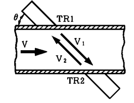
The ultrasonic flow measurement uses two transducers (TR1 and TR2) to measure the time it takes for an ultrasonic signal to travel upstream and downstream in a pipe.
Key points:
- V1: Ultrasonic speed from upstream to downstream (slower due to flow).
- V2: Ultrasonic speed from downstream to upstream (faster due to flow).
- θ: Angle of the sensor.
- V: Flow speed in the pipe.
- C: Speed of sound in the liquid.
Principle:
- The ultrasonic wave travels faster downstream (with the flow) and slower upstream (against the flow).
- The difference in travel times between upstream and downstream is proportional to the flow speed VVV.
Flow Rate Calculation:
- The flow speed VVV is calculated from the time difference: V=(V2−V1)2V = \frac{(V2 - V1)}{2}V=2(V2−V1)
- Volumetric flow rate QQQ is then calculated by: Q=V×AQ = V \times AQ=V×A where AAA is the pipe's cross-sectional area.
This method accurately measures flow by comparing ultrasonic travel times.
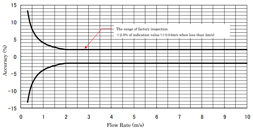
(Note) This is calibrated by manufacture’s factory inspection facility before delivery.
Please use calibration function if you find instrumental error due to operating environment.
Note) Pipe line shall be filled by liquid, and flow rate shall be ideal distribution.
Flow rate conversion table
Piping example/ Material: SGP Liquid: Water Value: Unit m3/H
|
Nominal Size |
Internal diameter |
Flow Rate (m/s) |
|||||||||
|
A |
mm |
1 |
2 |
3 |
4 |
5 |
6 |
7 |
8 |
9 |
10 |
|
15 |
16.1 |
0.7 |
1.5 |
2.2 |
2.9 |
3.7 |
4.4 |
5.1 |
5.9 |
6.6 |
7.3 |
|
20 |
21.6 |
1.3 |
2.6 |
4.0 |
5.3 |
6.6 |
7.9 |
9.2 |
10.6 |
11.9 |
13.2 |
|
25 |
27.6 |
2.2 |
4.3 |
6.5 |
8.6 |
10.8 |
12.9 |
15.1 |
17.2 |
19.4 |
21.5 |
|
32 |
35.7 |
3.6 |
7.2 |
10.8 |
14.4 |
18.0 |
21.6 |
25.2 |
28.8 |
32.4 |
36.0 |
|
40 |
41.6 |
4.9 |
9.8 |
14.7 |
19.6 |
24.5 |
29.4 |
34.3 |
39.1 |
44.0 |
48.9 |
|
50 |
52.9 |
7.9 |
15.8 |
23.7 |
31.6 |
39.6 |
47.5 |
55.4 |
63.3 |
71.2 |
79.1 |
|
65 |
67.9 |
13.0 |
26.1 |
39.1 |
52.1 |
65.2 |
78.2 |
91.2 |
104.3 |
117.3 |
130.4 |
|
80 |
80.7 |
18.4 |
36.8 |
55.2 |
73.7 |
92.1 |
110.5 |
128.9 |
147.3 |
165.7 |
184.1 |
|
100 |
105.3 |
31.4 |
62.7 |
94.1 |
125.4 |
156.8 |
188.1 |
219.5 |
250.8 |
282.2 |
313.5 |
|
125 |
130.8 |
48.4 |
96.7 |
145.1 |
193.5 |
241.9 |
290.2 |
338.6 |
387.0 |
435.4 |
483.7 |
|
150 |
155.2 |
68.1 |
136.2 |
204.3 |
272.4 |
340.5 |
408.6 |
476.7 |
544.8 |
612.9 |
681.0 |
|
200 |
204.7 |
118.5 |
237.0 |
355.4 |
473.9 |
592.4 |
710.9 |
829.3 |
947.8 |
1066.3 |
1184.8 |
|
250 |
254.2 |
182.7 |
365.4 |
548.1 |
730.8 |
913.5 |
1096.2 |
1278.9 |
1461.6 |
1644.3 |
1827.0 |
|
300 |
304.7 |
262.5 |
525.0 |
787.5 |
1050.0 |
1312.5 |
1575.0 |
1837.5 |
2100.0 |
2362.5 |
2625.0 |
|
350 |
339.8 |
326.5 |
652.9 |
979.4 |
1305.9 |
1632.3 |
1958.8 |
2285.3 |
2611.7 |
2938.2 |
3264.7 |
|
400 |
390.6 |
431.4 |
862.8 |
1294.1 |
1725.5 |
2156.9 |
2588.3 |
3019.6 |
3451.0 |
3882.4 |
4313.8 |
|
450 |
441.4 |
550.9 |
1101.8 |
1652.6 |
2203.5 |
2754.4 |
3305.3 |
3856.2 |
4407.0 |
4957.9 |
5508.8 |
|
500 |
492.2 |
685.0 |
1370.0 |
2054.9 |
2739.9 |
3424.9 |
4109.9 |
4794.8 |
5479.8 |
6164.8 |
6849.8 |
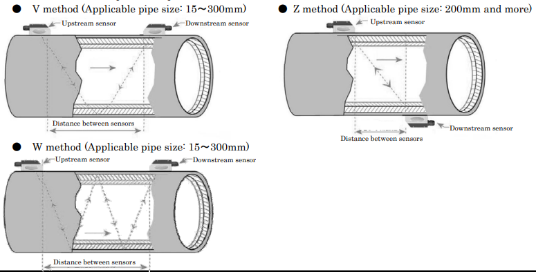
(1)Please select suitable installation method for piping condition in order to measure correctly. Please select from V
method, Z method and W method as below.
※ Extension rail as an option is required for Z method.
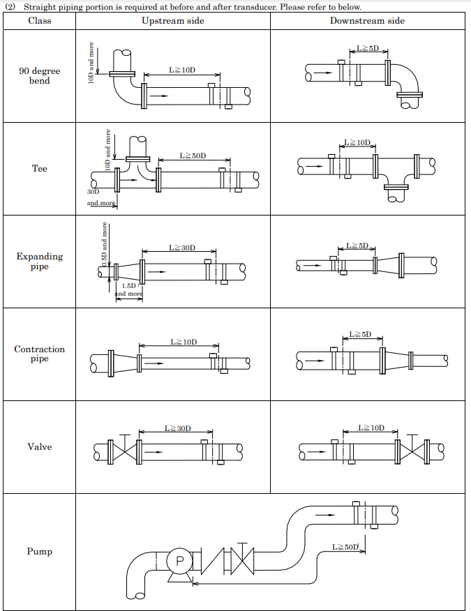
(2) Straight piping portion is required at before and after transducer. Please refer to below.
(3)Ambient temperature shall not exceed specification temperature. Less thermal variation is preferable.
(4)Please install to the pipe less obstacle of ultrasonic such as rust or scale. In case of impossibility, please set obstacle
as a liner, and measurement accuracy is equivalent of specification. However, please clean a pipe as possible.
(5)Space between pipe and liner makes difficulty of measurement because of less propagation of ultrasonic.
(6)Please select the place where pipe is filled by liquid while liquid does not flow. And also, please avoid to install the
place where may appear air bubbles.
(7)Please avoid to install sensor at right above and right under of the pipe in order to avoid air pocket and sediments.
Sensor shall be installed side within 90 degree angle from horizontal. And also, please avoid installation at a joint of flange or welded part of pipe.
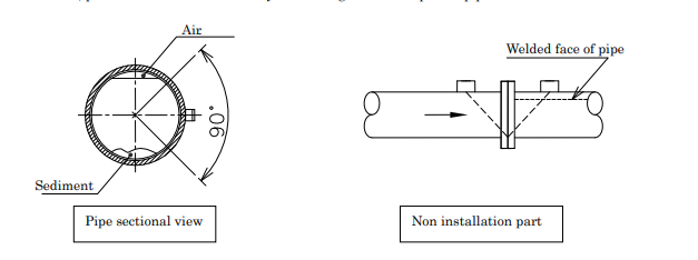
(8) Please apply acoustic coupler to sensor when install transducer. When apply the acoustic coupler, please be careful not to include air.

|
Model |
Code |
Specification |
||
|
NU2 |
|
Ultrasonic flow meter |
||
|
Type |
000 |
|
Clump-on type |
|
|
Transmitter |
SW |
|
Wall mount |
|
|
HD |
|
Hand held |
||
|
Transducer |
HSO HMO |
For pipe size: 15~ 100mm For pipe size: 50~ 600mm |
||

